

 See My Latest Article on HelloNation
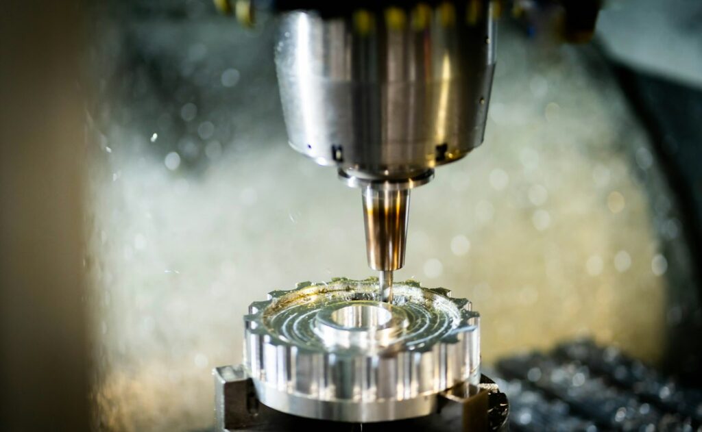
What do CAD and CAM mean in CNC machining?
CAD and CAM are the digital tools that connect an idea to a finished machined part. CAD creates the digital design, while CAM converts that design into instructions a CNC machine can follow.
CAD stands for computer-aided design. It is used to create a detailed 2D drawing or 3D model that defines a part’s size, shape, holes, curves, surfaces, and other features.
CAM stands for computer-aided manufacturing. It uses the CAD model to develop toolpaths, cutting conditions, machine movements, and other instructions needed to produce the part from metal, plastic, wood, or another material.
A CNC machine does not understand a general drawing or a verbal description. It needs precise machine code, commonly called G-code, along with information about tools, workholding, speeds, feeds, and coordinate positions. CAM software helps generate that information.
How does the process work from design to finished part?
The process usually follows a series of connected steps. Each step affects the accuracy, cost, and reliability of the final result.
1. Creating the CAD model
The process begins with a digital model or drawing. The designer defines dimensions, tolerances, material assumptions, hole locations, wall thicknesses, and surface features.
A useful CAD model contains more than a visually attractive shape. It should also communicate manufacturing requirements. For example, a narrow internal corner may look acceptable in a model but be difficult to machine because most cutting tools are round rather than square.
2. Reviewing the design for manufacturability
Before CAM programming begins, the design is reviewed to identify features that could create problems during machining. This review may consider:
- Whether a cutting tool can reach each feature
- Whether the part can be held securely
- Whether the specified tolerances are practical
- Whether thin walls could vibrate or deform
- Whether internal corners need a radius
- Whether the material is suitable for the intended process
- Whether the part requires multiple setups or orientations
This stage is often called design for manufacturability, or DFM. It can prevent unnecessary rework by identifying problems while changes are still easy to make.
3. Building CAM toolpaths
CAM software analyzes the CAD geometry and creates toolpaths. A toolpath is the planned route a cutting tool will take through or around the material.
Different operations may be used for different features:
- Facing removes material from the top surface.
- Pocketing clears material from an enclosed area.
- Profiling cuts around the outside edge of a part.
- Drilling creates holes at specified locations.
- Contouring follows curved or sloped surfaces.
- Thread milling produces internal or external threads.
- Engraving creates marks, lettering, or shallow details.
The programmer selects tools and sets cutting parameters such as spindle speed, feed rate, depth of cut, and step-over. The goal is to remove material efficiently without causing excessive heat, vibration, tool wear, or damage to the part.
4. Simulating the machining process
Before sending code to a CNC machine, CAM software can simulate the planned operation. Simulation helps reveal collisions, excessive material, missed areas, gouges, and incorrect tool movements.
This is especially useful for parts that require several tools or multiple setups. A collision between a tool holder and the workpiece may not be obvious from the CAD model alone. Simulation provides a way to test the sequence digitally before material and machine time are used.
5. Setting up and inspecting the part
The digital instructions still require careful physical setup. The operator installs the correct tools, secures the raw material, establishes work offsets, confirms tool lengths, and verifies the program.
After machining begins, the first part is commonly inspected. Measurements may be taken with calipers, micrometers, height gauges, gauges, or coordinate-measuring equipment, depending on the required accuracy.
If the measured part differs from the CAD design, adjustments may be needed in the setup, tool compensation, cutting conditions, or original model.
Why is CAD/CAM useful for CNC machining?
CAD/CAM improves consistency because the machine follows a defined digital plan rather than relying entirely on manual positioning. The same model and machining strategy can also be used to produce repeat parts, provided the material, setup, tools, and machine conditions remain controlled.
The software also makes complex geometry more practical. Curved surfaces, angled features, blended transitions, and irregular contours can be difficult to calculate manually. CAM systems can generate coordinated movements across several axes to machine these shapes.
Another advantage is traceability. Digital files can preserve the part model, revision history, toolpaths, inspection notes, and manufacturing changes. This helps distinguish an approved design from an older or unverified version.
That distinction matters in settings where a small change—such as a hole diameter or mounting position—could affect how the part fits or functions.
Does CAD/CAM guarantee an accurate part?
No. CAD/CAM can improve accuracy, but it does not guarantee that the finished part will match the design.
Accuracy depends on several factors:
- The quality of the CAD model
- Correct interpretation of dimensions and tolerances
- Machine condition and calibration
- Tool sharpness and runout
- Material behavior during cutting
- Workholding stability
- Proper setup and work offsets
- Temperature and vibration
- Inspection methods

A model may be mathematically precise while still being difficult to manufacture. Likewise, an error in the CAD file can be reproduced consistently by CAM and the CNC machine.
For this reason, digital simulation and physical inspection serve different purposes. Simulation checks the planned process, while inspection checks the actual result.
What local conditions can affect CNC work in Grand Rapids?
Seasonal temperature changes can affect machining and measurement, particularly for parts with tight tolerances. Metal expands and contracts as temperature changes, so a part measured in a warm production area may not measure exactly the same after reaching a cooler storage or work environment.
Humidity can also matter. Some materials, especially certain plastics and wood products, may absorb moisture and change dimensionally. Ferrous metals require appropriate storage and handling to reduce the risk of corrosion during humid periods.
For local workshops, garages, and small manufacturing spaces, power quality, floor stability, ventilation, and temperature control can also influence results. A compact CNC machine may appear straightforward to operate, but it still needs a stable environment and carefully controlled setup to produce repeatable work.
What common misconceptions should beginners avoid?
One misconception is that CAD and CAM are interchangeable. CAD describes the part; CAM describes how the machine will make it. They work together but solve different problems.
Another misconception is that a perfect-looking 3D model automatically contains everything needed for production. Manufacturing may also require material specifications, tolerances, surface-finish requirements, datums, thread information, and inspection criteria.
It is also easy to assume that more machine axes always produce better results. Additional axes can improve access and reduce setups, but they also increase programming complexity and require appropriate post-processing and machine control.
Finally, automation does not eliminate judgment. Experienced machining decisions are still needed to select tools, control cutting forces, plan workholding, recognize risky geometry, and verify the finished part.
How should someone evaluate a CAD/CAM file before machining?
A practical review should confirm that the file includes:
- Correct units, such as inch or millimeter
- A complete and current revision
- Clearly defined critical dimensions
- Realistic tolerances
- Material information
- Surface-finish requirements where needed
- Hole, thread, and radius details
- Adequate access for cutting tools
- A workable setup and workholding plan
- A method for inspecting critical features
The strongest CAD/CAM workflow treats the digital model, machining plan, physical setup, and inspection process as one connected system. Each part of that system must agree before the cutting begins.